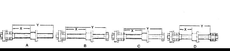
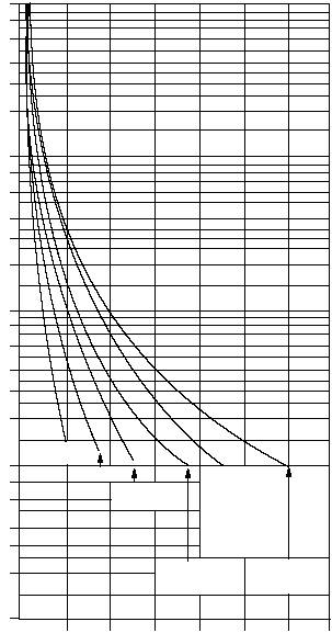
Techno Linear Motion Catalog14Technical InformationCRITICAL SPEEDPURPOSEThis graph was designed to simplify theselection of the proper lead screw so asto avoid lengths and speeds which willresult in vibration of the assembly(critical speed). The factors which canbe controlled after a particularmaximum length is determined are:method of bearing support and choiceof lead screw diameter.USE OF THE GRAPH1. Choose preferred bearing supportmeans, based on designconsiderations.2. On the proper bearing supporthorizontal line (A, B, C or D) chooselength of lead screw.3. Draw vertical line at the lead screwlength, determined at (2.), and drawa horizontal line at the travel rate.4. All screw diameters to the right andabove the intersection point in (3.)are suitable for this application.5. Screw sizes are coded as follows:Diameter (in)Threads / inStartsTravel Rate vs. LengthFor Standard ACME Screws1000008000060000400003000020000100008000600040003000 2000 1000 800 600 400 300 200 100 80 60 40 30 20 10 2516125161371613710131084370844308250101621017510137122 31032370816210275061ONE END FIXEDOTHER END FREEONE END FIXEDOTHER END SUPPORTED BOTH ENDS SUPPORTEDBOTH ENDS FIXEDREFAREFBREFCREFD61012151218244048603036452024303036427085105607390506175INCHESINCHESINCHESINCHESLENGTHMAXIMUM LENGTH (IN.) ADJUSTED FOR BEARING SUPPORT“Y” DIMENSION