14
www.techno-isel.com
Technical Information
L
–––
2
L
–––
4
L
–––
2
L
–––
4
d3
–––
d1
(
)
d3
–––
d1
(
)
L
–––
4
L
–––
2
d4
d2
d3
d4
F1
F3
F2
F4
L
F1S
F2S
F2
F1
F3
d1
TO CENTER
OF SCREW
FROM CENTER
OF TABLE
d2
F4S
F2
F2S
F1S
L
F1
F3
F4
L
d1
d3
d1
d3
d4
d2
F3S
F4
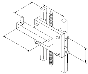
Horizontal Translation with Side Load: when a side
load is applied to the bearing system, the loads on the
individual bearings change, and new equations are
required. Each bearing will have a resultant normal load
as well as a side load. The orientation of the applied
load with respect to the bearing system is the important
feature to consider. This means that these equations can
still be used even if the orientation of the translation is
not horizontal, as long as the load to bearing relationship
is preserved.
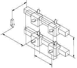
VerticalTranslation with Vertical Load: when the load
is applied in the direction of travel (thrust), then the
following equations should be used to calculate the loads
on each bearing block. This type of configuration is
generally found in vertical applications. The orientation
of the applied load with respect to the bearing system is
the important feature to consider. This means that these
equations can still be used even if the orientation of the
translation is not vertical, as long as the load to bearing
relationship is preserved.
F2 =
+
L
–––
4
L
–––
2
d4
–––
d2
F1 =
+
d3
–––
d1
(
)
d4
–––
d2
F3 =
d4
–––
d2
L
–––
4
L
–––
2
d3
–––
d1
d4
–––
d2
F4 = + +
( )
F2S = F4S =
d3
–––
d1
( )
F1S = F3S =
+
L
–––
4
d3
–––
d1
( )
L
–––
2
F3 = F4 =
L
–––
2
d4
–––
d2
( )
F1 = F2 =
L
–––
2
d4
–––
d2
( )
F1 = F3 =
L
–––
2
d3
–––
d1
( )
F2 = F4 =
L
–––
2
d3
–––
d1
( )
F1S = F3S =
L
–––
2
d4
–––
d2
( )
F2S = F4S =
L
–––
2
d4
–––
d2
( )
(7)
(8)
(9)
–
–
–
–
–
–
–
–
FORMAT 1
FORMAT 2
FORMAT 3