Technical Information
techquestions@techno-isel.com
23
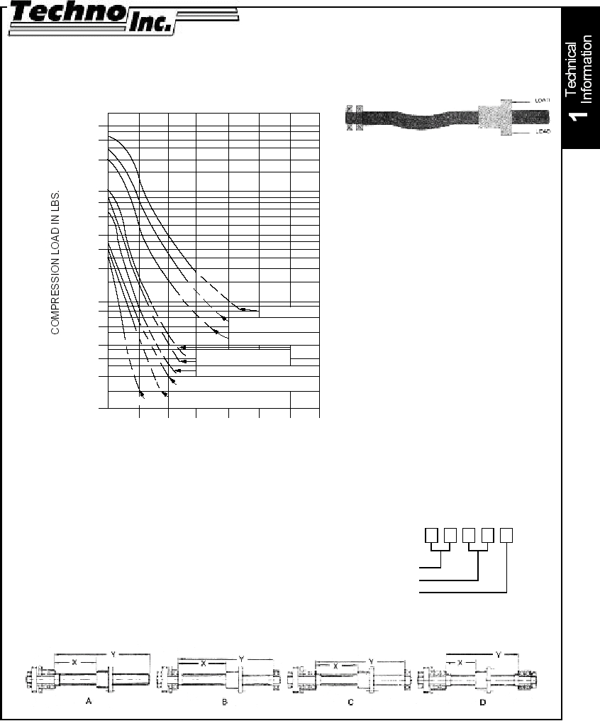
PURPOSE
This graph was designed to simplify the
selection of the proper lead screw so as
to avoid buckling when subjected to the
axial loading by means of the nut. The
factors which can be controlled after a
particular maximum length is
determined are: method of bearing
support and choice of lead screw
diameter.
USE OF THE GRAPH
1. Choose preferred bearing support
means, based on design
considerations.
2. On the proper bearing support
horizontal line (A, B, C or D) choose
length of lead screw.
3. Draw vertical line at the lead screw
length, determined at (2.), and draw
a horizontal line at the compression
load the unit is exerting on the
screw.
4. All sizes to the right and above the
intersection point in (3.) are suitable
for this application.
5. Screw sizes are coded as follows:
Diameter (in)
Threads / in
Starts
MAXIMUM LENGTH (IN.) ADJUSTED FOR BEARING SUPPORT
"X" DIMENSION
Compression Load vs. Length
FOR STANDARD BALL SCREWS & ACME SCREWS
COLUMN LOADS
75101
75061
62081
62101
62102
50101
75081
43082
43084
37161
37081
37101
37121
31082
81084
31122
37122
37084
25161
40000
30000
20000
10000
8000
6000
4000
3000
2000
1000
800
600
400
300
200
100
ONE END FIXED
OTHER END FREE
REF
A
REF
B
REF
C
REF
D
5
10
14
20
10
20
28
40
15
30
42
60
20
40
57
80
25
50
71
100
30
60
85
120
INCHESINCHES
INCHES
INCHES
INCHES
BOTH ENDS SUPPORTED
ONE END FIXED
OTHER END SUPPORTED
BOTH ENDS FIXED
LENGTH