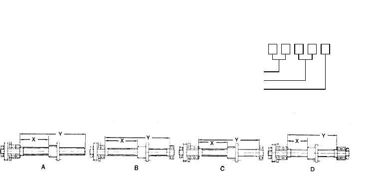
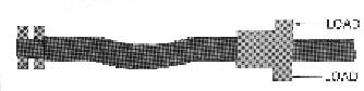
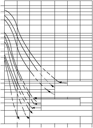
Techno Linear Motion Catalog15Technical InformationCompression Load vs. LengthFor Standard Ball Screws and ACME ScrewsCOLUMN LOADSMAXIMUM LENGTH (IN.) ADJUSTED FOR BEARING SUPPORT“X” DIMENSIONPURPOSEThis graph was designed to simplify theselection of the proper lead screw so asto avoid buckling when subjected to theaxial loading by means of the nut. Thefactors which can be controlled after aparticular maximum length isdetermined are: method of bearingsupport and choice of lead screwdiameter.USE OF THE GRAPH1. Choose preferred bearing supportmeans, based on designconsiderations.2. On the proper bearing supporthorizontal line (A, B, C or D) chooselength of lead screw.3. Draw vertical line at the lead screwlength, determined at (2.), and drawa horizontal line at the compressionload the unit is exerting on thescrew.4. All screw diameters to the right andabove the intersection point in (3.)are suitable for this application.5. Screw sizes are coded as follows:Diameter (in)Threads / inStarts751017506162081 62101 62102501017508143082 430843716137081 37101 37121310828108431122 37122370842516140000300002000010000800060004000300020001000800600400300200100ONE END FIXEDOTHER END FREEREFAREFBREFCREFD5101420102028401530426020405780255071100306085120INCHESINCHESINCHESINCHESINCHESBOTH ENDS SUPPORTEDONE END FIXEDOTHER END SUPPORTEDBOTH ENDS FIXEDLENGTH