Technical Information
techquestions@techno-isel.com
17
Selecting A Linear Bearing System
Nominal Life Expectancy
The nominal life expectancy is achieved, or
exceeded a majority of 90% of the nominal life
expectancy, before the first indication of fatigue of
material appears.
L =
C
x
(1)
P
Lh = 833
(2)
H · nosz
Lh = 1666
(3)
V
L [m]
nominal life expectancy in 100,000 m
Lh [h]
nominal life expectancy in operating hours
C [N]
dynamic load data
P [N]
dynamic equivalent load
x
life expectancy index:
ball-bearing linear guides: x = 3
roller-bearing linear guides: x = 10/3
H [m]
single stroke length of the oscillated
movement
nosz [min] number of the double strokes per minute
V [m/min] average travel speed
Usable Life
The actual life expectancy achieved by a linear guide
is known as usable life. The usable life can deviate
from the calculated life expectancy.
Wear & tear or fatigue can lead to early defects:
- alignment error between the guide rails or the
guide elements
- insufficient lubrication
There are several factors in selecting a Linear Bearing System.
Here are the main items to consider ...
• Travel
• Load
• Orientation
• Maximum Speed
• Minimum Acceleration
• Environment
- oscillated movement with very small strokes
(rippling)
- vibration during standstill (rippling)
Due to the variation in installations and operating
conditions, it is not possible to determine the exact
usable life of a linear guide in advance. The safest
method to obtain a correct assessment of the usable
life is to compare cases with similar installation.
Combined Loading Capacity
(4)
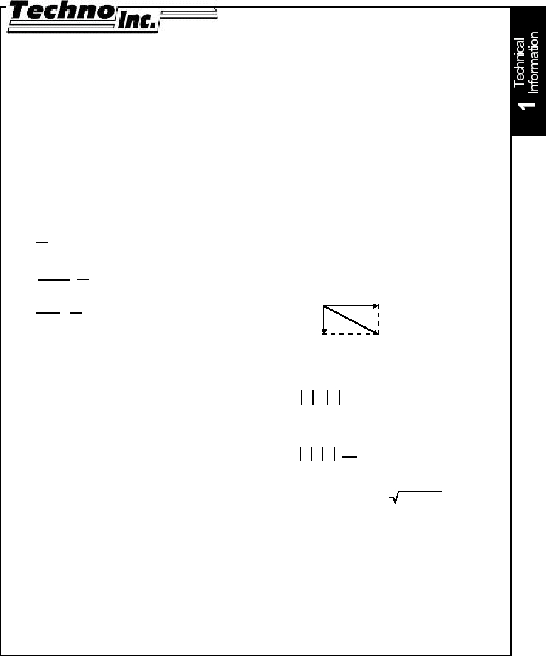
When the loading direction of an element does not
coincide with one of the main loading directions, the
equivalent load is calculated as follows:
P = F1 + F2
(5)
When a Force (F) and a moment (M) are applied at
the same time, the dynamic equivalent load is:
P = F + M C0
M0
(6)
P [N]
dynamic equivalent load
F [N]
applied force =
F1
2
+ F2
2
F1 [N]
vertical components, see sketch (4)
F2 [N]
horizontal components, see sketch (4)
C0 [N]
static load in the direction of the applied
force
M [Nm] applied moment
M0 [Nm] static moment in the direction of the applied
moment
According the DIN, the dynamic equivalent load
should not exceed the value P= 0.5 C
For multiple Rail and Carriage Configurations, refer
to page 14
( )
( )
C
x
P
( )
C
x
P
F1
F2
F
·
·